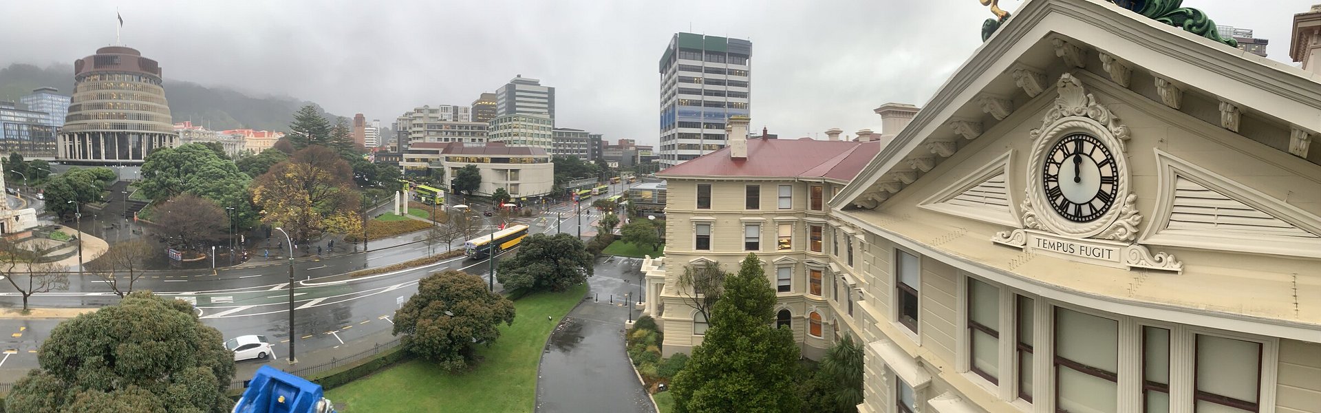
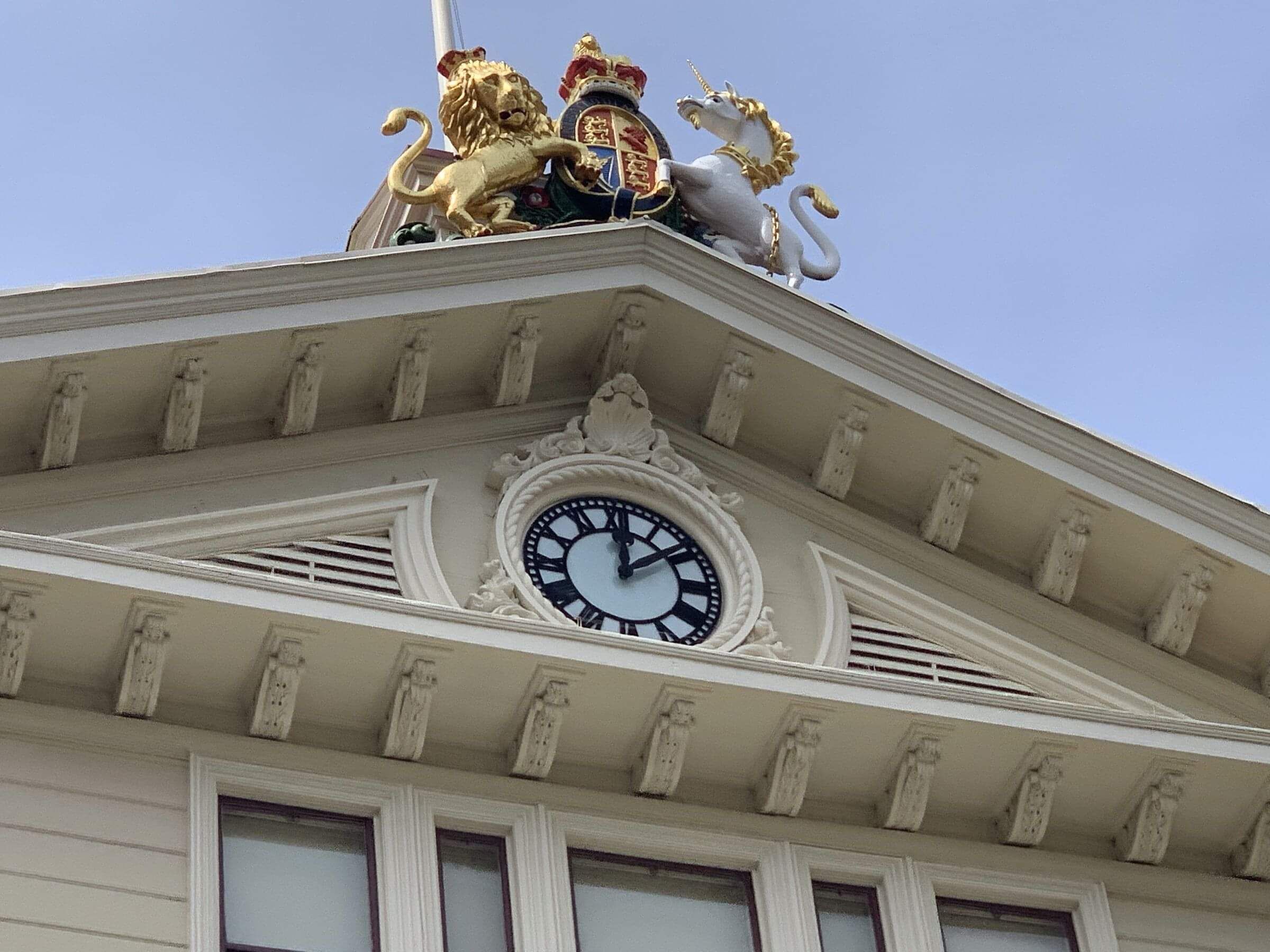
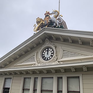
WELLINGTON'S OLD GOVERNMENT BUILDING CLOCK - THE CLOCK THAT COVID STOPPED.
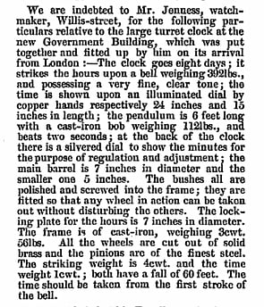
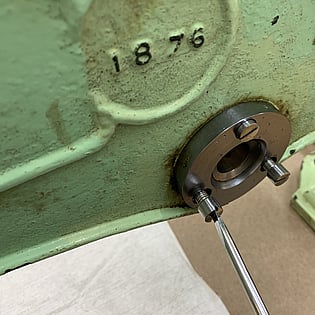
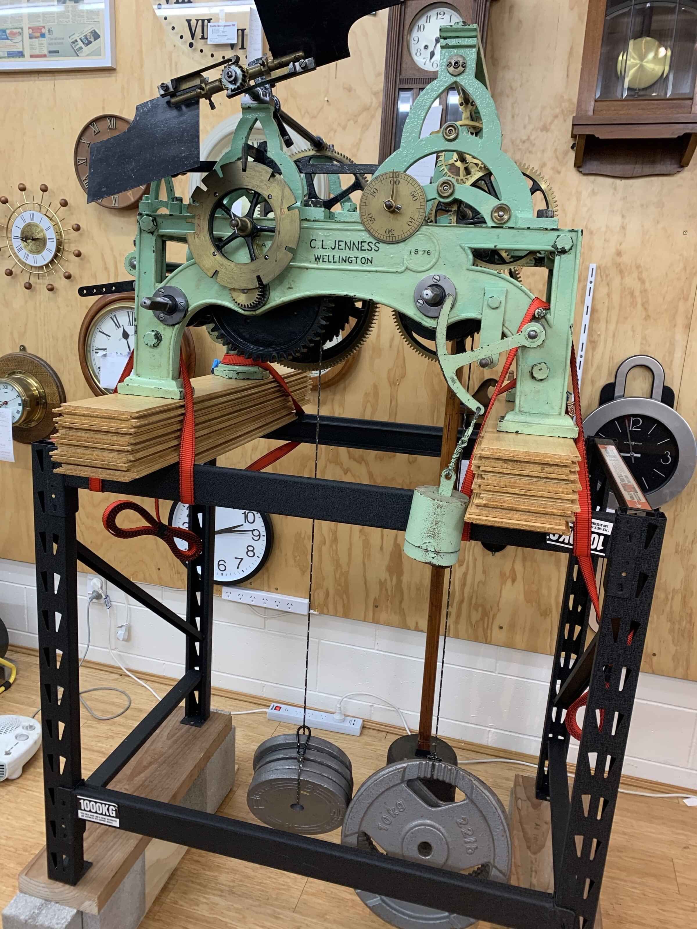
In early 2020 we won a tender from Heritage New Zealand to complete an overhaul of the historic clock in the roof of the Old Government Building in Wellington. The clock was made by Gilet and Bland of Croydon, London in 1876, and installed in 1877, and has been in continuous operation (barring removal for servicing) ever since.
In March 2020 as New Zealand went into level 4 lockdown due to COVID19, for the first time in over a century the clock was left to run down and stop. We were forced to wait until the country went into level 2 before we could return to Wellington and remove the clock for servicing, by which time it had been stopped and silent for several weeks.
Learn more about the Building on Heritage New Zealand Website
STEP ONE - REMOVAL
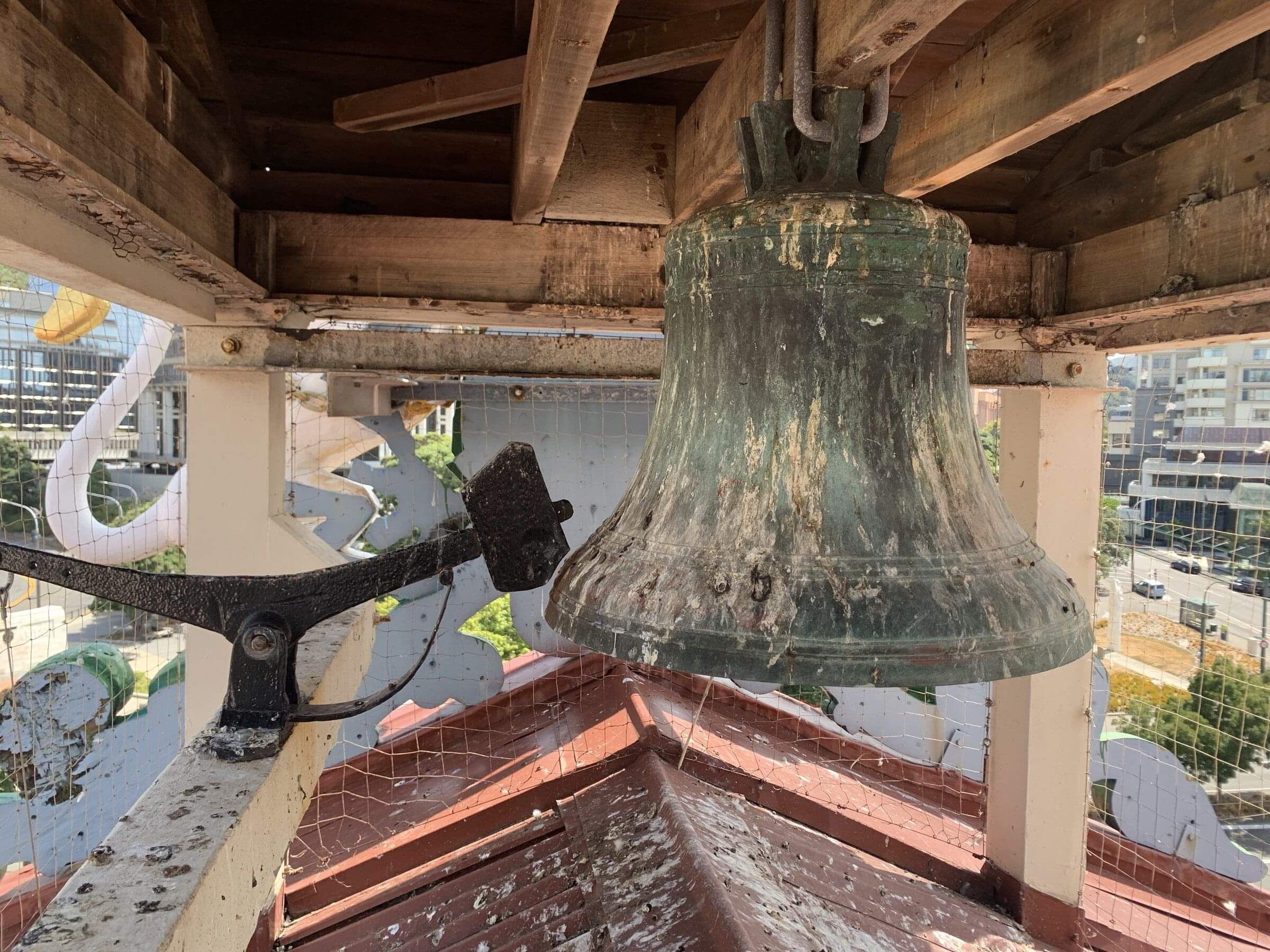
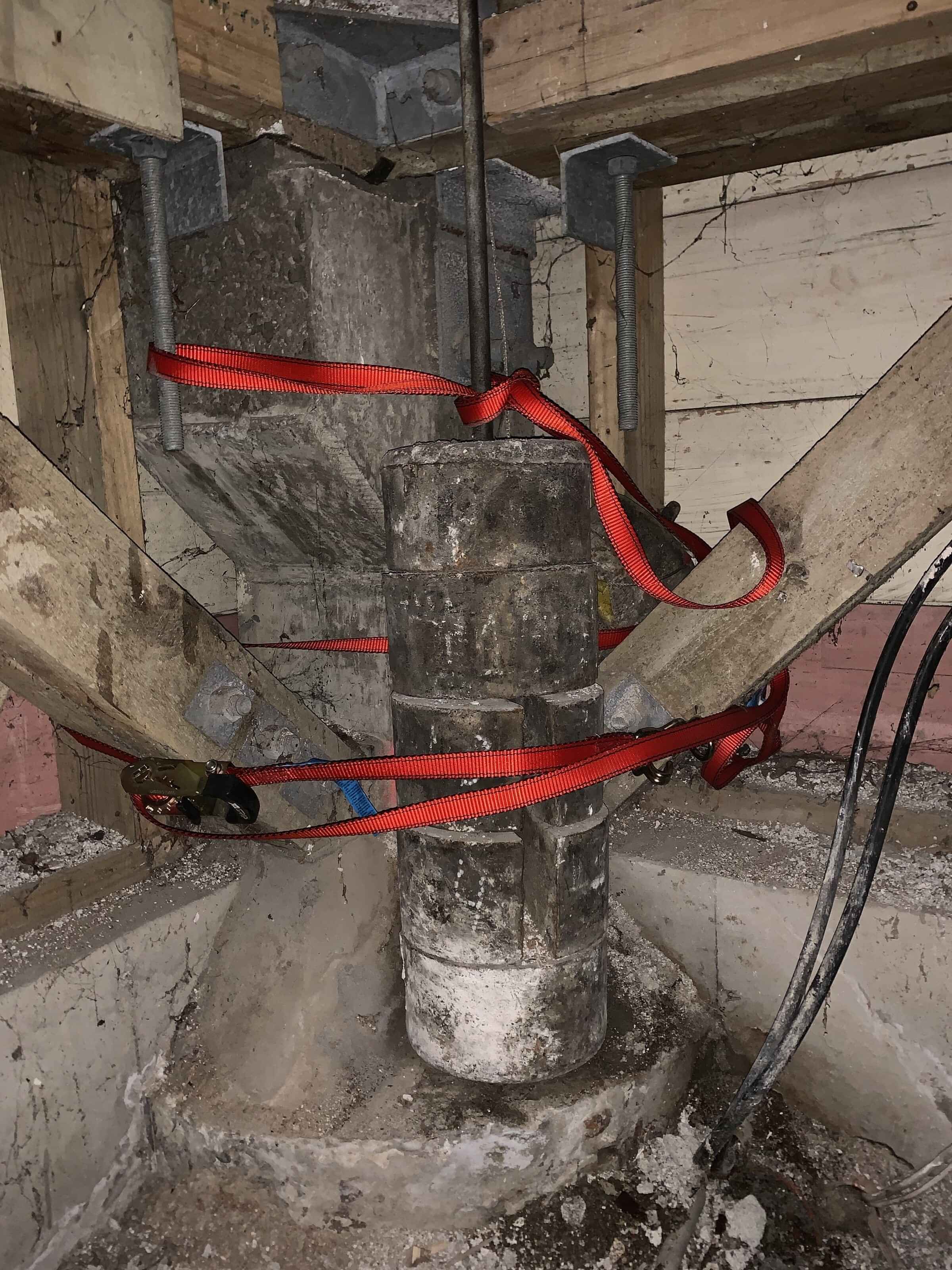
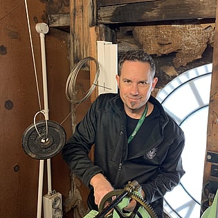
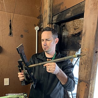
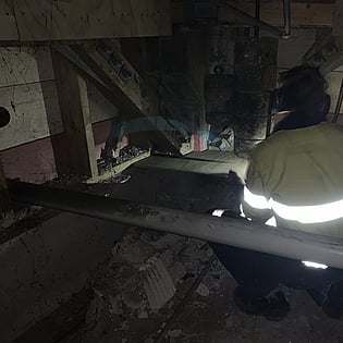
On May 29 Wellington watchmaker Graeme Robertson and I dismantled and removed the clock for servicing. While Graeme had removed the hands the previous day, we first set about removing some built up concrete slag from the pillar in the basement where the very heavy weights land, and then levelling off a safe landing spot. If both weights touch down and tip over they can tangle up the cables, or even worse, the cables could come off their pulleys. This was something we wanted to avoid, as sorting out the mess could be difficult and potentially dangerous. The time weight had landed during lockdown, while the extremely heavy striking weight was mercifully still about 2 feet off the ground. While Graeme stayed underneath to administer the touchdown of the striking weight, I went up into the clock room to disconnect the bell cable and allow the strike gear train to run continuously until the weight touched down.
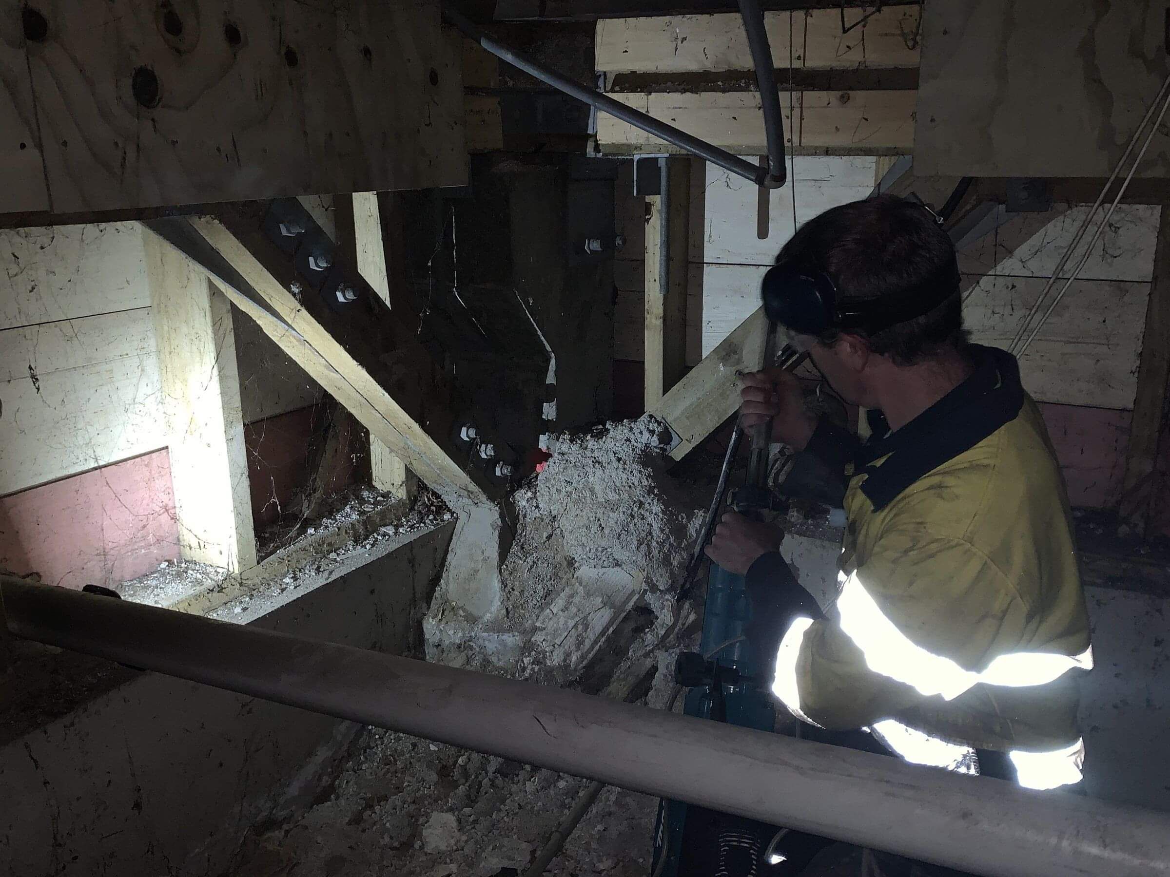
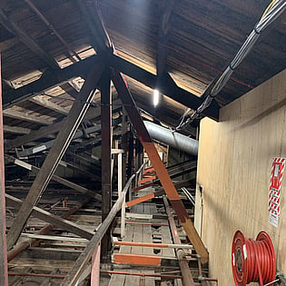
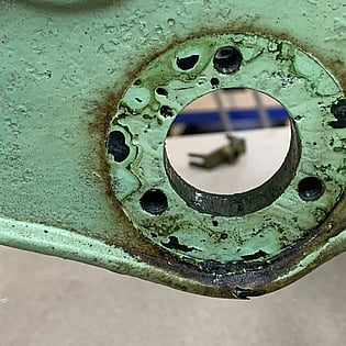
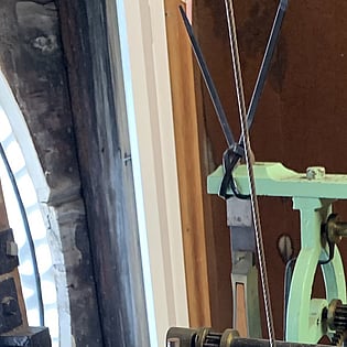
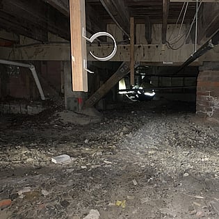
The weights drop 60 feet though a narrow tunnel and land in the basement. Here, the going weight is tucked behind the much larger striking weight, which has been secured.
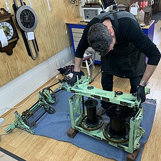
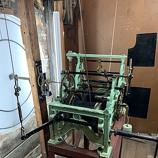
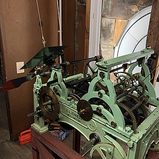
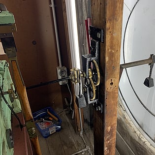
After securing the weights and releasing the cables, we set about dismantling and removing the clock movement. This involved carrying the heavy components through the roof space of the building over and under numerous support struts, and down a narrow staircase, before being carefully loaded into my vehicle. The process took several hours.
STEP TWO - SERVICING
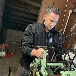
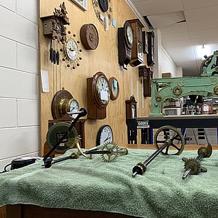
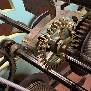
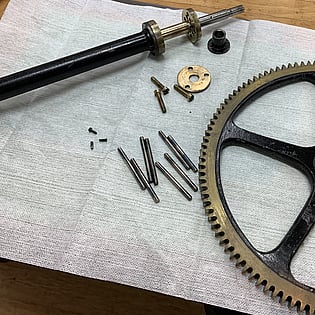
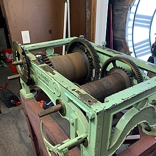
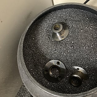
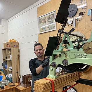
Most of the work involved in servicing the clock revolved around stripping the movement right down and doing a really good deep clean. The clock is up in a dusty roof space and it gets very contaminated by dust over the years. This fouls the oil and creates grinding paste which eventually wears certain components.
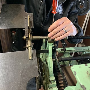
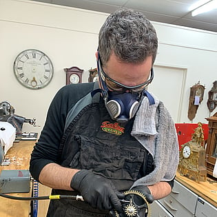
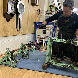
I worked on one section of the clock at a time (sort of) to make it easier to keep track of all the various parts. Everything was stripped right down for cleaning, including disassembling the lantern pinions. I was not able to use my normal clock cleaning solution for this job, as it would have immediately attacked the paint. After some consultation I settled on Kemsol Oil Clean from Jasco Distributing here in Rotorua. This did a great job emulsifying the oil and so I could scrub it off without ruining the patina or paint finish on the various parts. I used a mix of brushes including a bottle brush with nylon bristles for cleaning inside bushes, and spinning steel bristled brushes on my foredom tool and polishing motor to clean in between the teeth on all the gears.
There were two major areas on the clock that needed some extra attention. The first was the escapement. This consists of two major components: The pallets and the escape wheel. This clock uses a dead-beat escapement, which means one escape wheel tooth at a time is arrested by the pallet nibs as they rock back and forth. The escape wheel should not recoil at all as the nib slides up the tooth... It should stop dead - hence the name dead-beat. Because the sliding faces on this clock escapement tend to get covered in dust, it has worn somewhat over the years. At some point the pallets have been ground to deal with wear, and the curve of them has been changed. This was causing recoil in the escape wheel and bending the teeth. I spent some time experimenting with shims, and adjusting the depthing, and then put the escape wheel in the lathe to help straighten the bent teeth by gently pinching and pulling outwards on each tooth with smooth jaw pliers. This resulted in a much improved interface with reduced recoil. Ideally, the escapement should run with absolutely no recoil, but that would mean new pallets and new escape wheel. This is a historical piece, and my aim was to change the clock as little as possible. At some point in the future these parts will need to be replaced, but I think it will keep going perfectly well with the existing components for some decades yet.
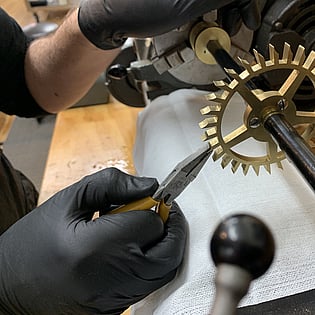
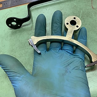
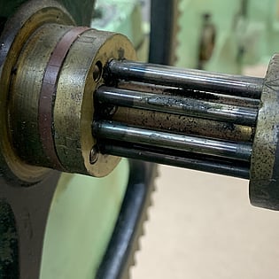
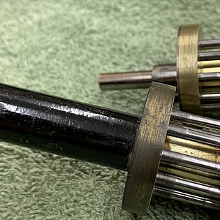
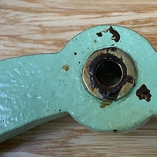
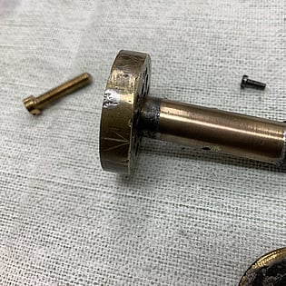
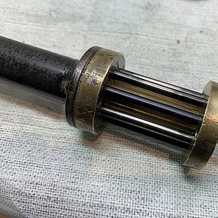
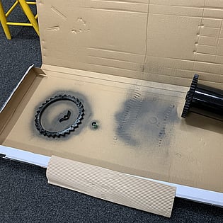
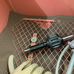
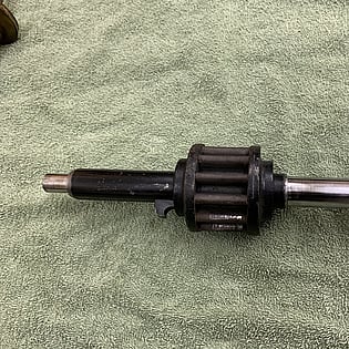
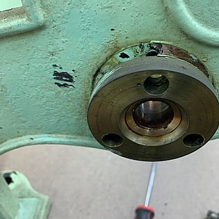
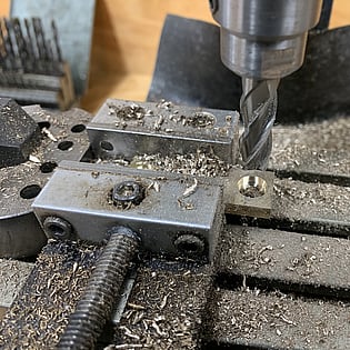
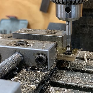
The second major repair I had to do was on a large lantern pinion on the striking train. When I first examined the clock I noticed that the teeth on the striking barrel great wheel were noticeably bent on one edge, but I couldn't figure out why. As I dismantled the pinion to clean it I found out why the teeth were bent. Pinions are wheels with normally 12 or less teeth... and the teeth are called leaves. They can be cut the same as a wheel, or made from steel rollers called trundles set into brass bobbins. This latter type are called lantern pinions, and while they are found in many low grade clocks as they are cheaper to make, they are actually very effective, and also found in high quality clocks such as this. The steel trundles should roll to minimise sliding friction and corresponding wear on the wheel teeth. A lot of these trundles were gunked up and not rolling, which is why I opted to dismantle them completely.
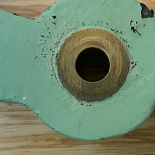
When I dismantled the largest pinion in the clock I found that the two ends of the bobbin were moving independently of each other causing the whole pinion to twist..... Not good. A closer inspection showed the two ends were lead soldered onto an ill-fitting brass core, and the solder joints had broken. Lead solder isn't very strong at the best of times and this pinion is driven by a wheel supporting a 200kg weight. I would never have discovered this if I hadn't decided to take the pinions apart for cleaning.
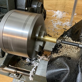
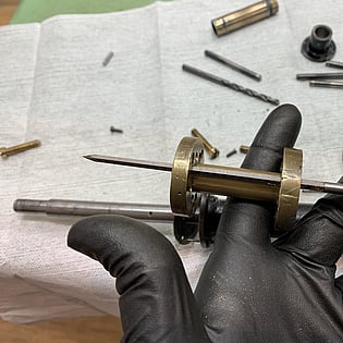
The remedy was to bore out the holes in the bobbin ends to uniform diameter, and machine a new brass core to a very tight press fit. I then pressed on the bobbin ends with ultra high strength stud lock. I tidied up the insides of the holes a bit with a reamer to make sure each trundle would roll nicely. It turned out that one of the trundles was an oversized replacement, so I discarded it and fitted a piece of blued steel of the correct diameter.
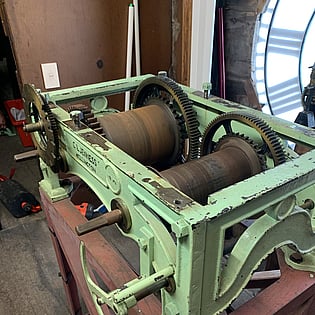
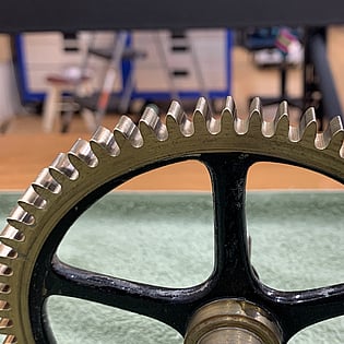
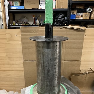
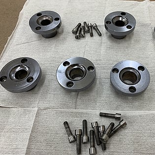
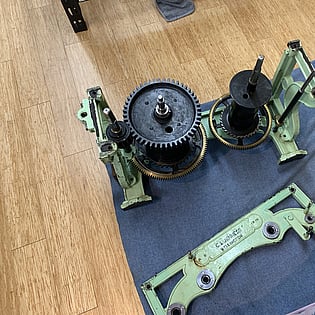
The main frame of the clock holds the barrels, maintaining power pinion, and the winding pinion for the strike. Because the striking weight is so heavy it is geared down, so when the clock is wound up it uses a pinion to turn the barrel. These lower components were somewhat rusty. Now I don't mind oxidation on the brass work - that is called patina. But I don't feel the same way about rust. That has to go. I used a mix of drill mounted and polishing motor mounted scotch-brite abrasive wheels, brass bristle wheels, steel bristle wheels, and finally a scotch-brite pad and steel wool to clean up the barrels and arbors, and I used my sandblast cabinet with agate media to clean up the leaves of the winding pinion. I was a bit pre-occupied with the task at hand for a lot of this and didn't think to take many photos.
I wasn't planning to do a lot of re-painting on the clock, as my job is to conserve it, not restore it. But since bare iron would soon oxidise again I opted to spray paint the barrels. They looked too shiny post spray so a bit of work with steel wool took the glossy edge off and gave the appropriate appearance.
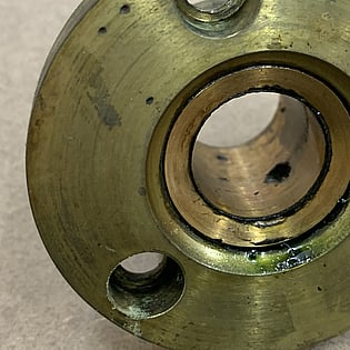
The large bushes in the main frame are cast brass items screwed into place. Each one is stamped with a number, which is a nice touch. The old oil was looking pretty bad, so all the bushes were removed and thoroughly cleaned. I opted for a molybdenum disulphide treatment on these, putting them into my turbo tumbler. I use this bullet coating media to treat all my clock mainsrpings and it makes them super slippery. The parts come out of the tumbler with a slippery coating of dry lube all over them. As the lubricating oil dries up over the years, the dry lube powder remains. It should extend the life of the bushes by many years.
STEP THREE - EARTHQUAKE PROOFING
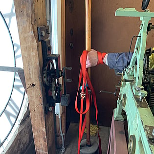
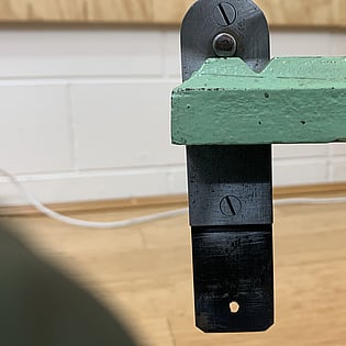
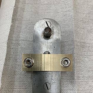
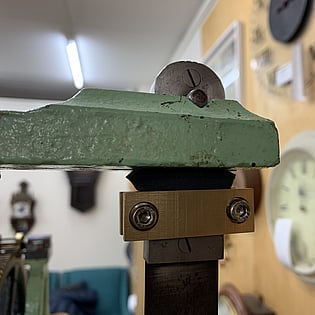
There was one very real risk with this clock. In the event of an earthquake it was possible for the pendulum to become dislodged from its hanger and fall. After a previous earthquake the pendulum was found to have jumped out of its slot and be sitting about 2mm away from falling off. Because the 50+kg pendulum hangs down into a hole in the floor with only some thin planks below it, it has the potential to fall right through the floor and keep going until it hit the basement. The current fix for this was to strap it in place with some heavy duty zip ties, but I was less than convinced about the effectiveness of these.I thought long and hard about how to mitigate this risk without doing anything invasive like drilling into the frame of the clock, and I finally settled on machining a clamp to go on the hanger block just above the suspension spring. After some discussion with others familiar with earthquakes in Wellington I opted to add a stiff foam ring above the clamp. This would allow some vertical movement between the pendulum and hanger, and reduce the risk of breaking the suspension spring. I am satisfied that this will be a neat and effective solution.
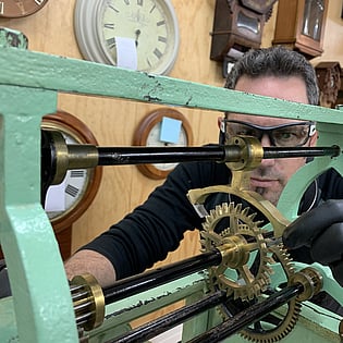
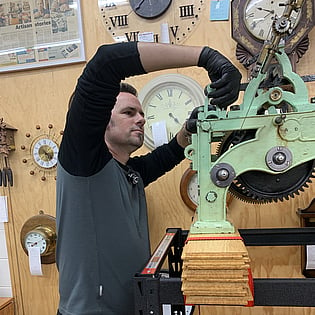
Having completed the repairs and cleaned all the parts, it was time to reassemble the clock and test it. I had to rig up a high enough (and sturdy enough) testing stand to accommodate the 6ft pendulum. After a bit of a search around to see what we had at hand (including a leftover box of bamboo floor panels from the workshop) we managed to get it up high enough. It did take four adults to lift the main frame with barrels up onto the stand, and for safety's sake I opted to lash it all in place.
I hung some weights from the barrels and drove the clock as well as I could. Without the hands and motion work attached I was able to drive the clock with significantly less weight, and since the strike was not pulling a cable to the hammer up on the roof it was able to run on only 20kg. The normal weight is 200kg but because of the pulley system there is only 100kg acting on the strike. The weight falls 60ft but feeds out 120ft of cable. I only had about 4 feet of fall to play with so both barrels needed frequent re-winding.
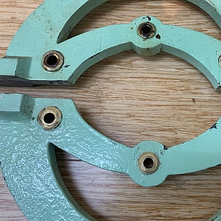
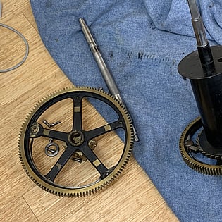
One of the reasons I was able to run the strike with so little weight was that I adjusted the vanes on the speed governor to offer less resistance. The gear train needs enormous torque to active the hammer, but then needs a way of preventing it from picking up too much speed. All chiming and striking clocks use these speed governors (called flies), but this is by far the largest I have ever come across. It uses a spring ratchet mechanism to bring it slowly to a stop when the gear train stops abruptly. If not for this the shock load through the gears would soon result in catastrophic failure.
STEP FOUR - REINSTALLATION
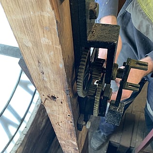
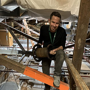
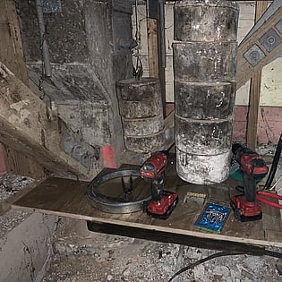
When testing was complete the clock was partially dismantled and packed into my car for the return trip south. Arriving in Wellington just after 5pm, I collected my pass key and set to work transporting the lighter components back up into the roof. Graeme soon turned up after a long day at work and together we transported the heavier components. This time we stripped the main frame right down and it was very much easier than carrying it down intact like we had the first time. It still took about three hours to lug everything up there and reassemble it. When the cables were reattached we wound it just enough to put some tension on them and then headed down to the basement. Part of the job I had suggested was to fabricate a platform under the weights so that in future when they needed to be let down for servicing, they would not fall over and tangle up the cables.
Graeme took the lead on this part of the job, fabricating a thick plywood platform to hold all 250 kilograms and keep the striking weight upright. I was up and down from basement to roof raising and lowering the weights to check positioning, and generally acting as assistant. It took a lot longer than anticipated, as is often the case and we finally finished somewhere approaching midnight. I left the clock ticking but with drive to the motion work decoupled so it would not strike during the night and we headed off to find some dinner. I was due back at the building at 8am to re-fit the hands.


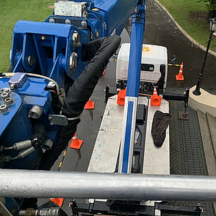
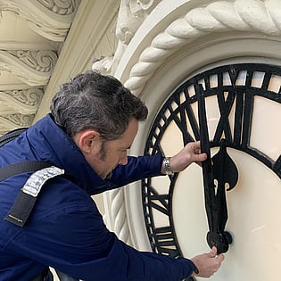
On a cold and wet Friday morning I was ready and waiting for the cherry picker to arrive at 8am. We were a bit worried about the forecast, as wind could make it too dangerous to maneuver the the basket up close to the building, but other than some drizzle it was fine. Ironically, fitting the hands was the easiest part of the whole business and too soon I was back on the ground.
All that remained was to go back up to the clock, adjust the hands and strike, and re-couple the drive. At 9am on the 19th of June the clock struck for the first time since the beginning of April.
My job was done.

There is still one small job left to do - and it's going to be mucky....